 Loading... Please wait...
- Home
- Leo Bodnar
- Precision GPS Reference Clock 精准GPS参考时钟
Product Description
Product Description
Low-jitter GPS-locked precision frequency reference
450 Hz to 800 MHz output
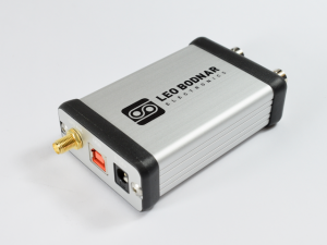
This device outputs two synchronised low-jitter reference clocks locked to GPS signal.
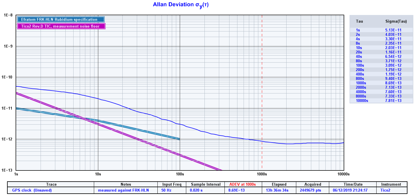
Long term stability of output signal is defined by high accuracy of GPS Caesium references and theoretically approaches 1x10-12.
Short term signal quality is defined by internal TCXO clock source providing high-quality, low phase noise clock signal with sub-picosecond RMS jitter.
Digital PLL allows main output reference frequency to have almost any value between 450Hz and 800MHz.
The second output frequency depends on the first output due to a common internal clock, if you need individual flexibility, multiple mini GPS units may be a better choice. If both outputs have the same frequency their relative phase shift can be adjusted. This can be used, for example, to generate two signals with 90° phase shift for use in I/Q mixer.
Both output signals square wave at 3.3V CMOS levels with 50 Ohms characteristic impedance. Their output drive levels can be adjusted and outputs can be enabled and disabled independently.
Output power level (measured at 10MHz, fundamental power channel):
+13.3dBm, drive setting 32mA
+12.7dBm, drive setting 24mA
+11.4dBm, drive setting 16mA
+7.7dBm, drive setting 8mA
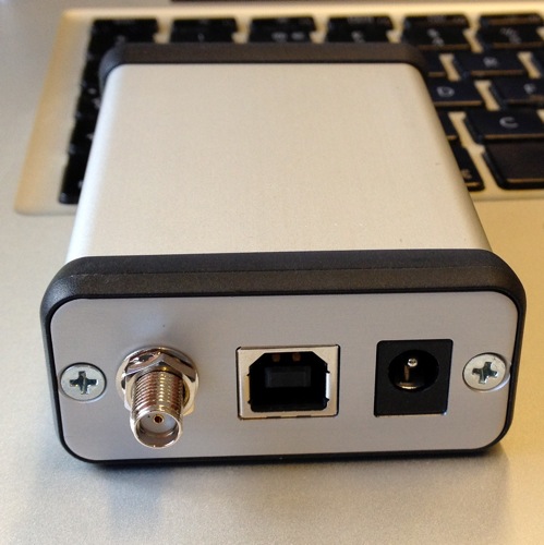
The device comes with USB cable and an active GPS antennna with magnetic base.
Operation requires continuous presence of GPS signal, however temporary loss will be tolerated seamlessly. Active or passive antennas are supported. An active antenna with 5 metre cable is provided with the device but can be substituted if necessary. GPS acquisition time after power-up is around 30 seconds. If GPS signal is lost, digital PLL will maintains best estimated output frequency based on historical data. On reacquisition of GPS lock, output is seamlessly brought back in sync with GPS reference. Entry and exit of frequency hold is glitch-less.
All frequency and output settings are fully user-configurable via USB connection from Windows PC.
GPS clock can be powered from USB input and/or external 5-12VDC power input. The DC connector parameters are: 2.5mm for the pin and 5.5mm on the outer diameter. USB connection to Windows PC is required only for one-off configuration. All settings are stored inside the device and maintain values when off. The SMA antenna connector voltage is 3.3V. Most active antennas have a wide range voltage input (2.5v to 5v) as they have an analogue LNA inside that is not sensitive to power level. If you are not connecting our antennas please check the antenna data sheet.
Examples of use include:
10.000MHz, 1.000MHz or other frequency reference for lab equipment and instrumentation
reference for transmitter equipment - HAM rigs, propagation beacons, frequency markers
reference for receiving equipment, RTL SDRs (28.8MHz) and band scanners
calibration source for radio receivers
master clock for audio and video equipment, DACs and studio recording gear
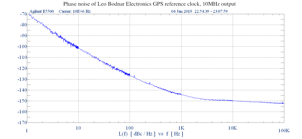
Measured phase noise of GPS clock at 10MHz output is equal or better than:
-70 dBc/Hz at 1 Hz offset from the carrier
-100 dBc/Hz at 10 Hz
-125 dBc/Hz at 100 Hz
-143 dBc/Hz at 1 kHz
-150 dBc/Hz at 10 kHz
-152 dBc/Hz at 100 kHz
-155 dBc/Hz at 1 MHz
Power draw through USB is 250mA
We are happy to advise whether specific combination of output frequencies are achievable via email. If you are not happy with your product for any reason just send it back and we will refund your purchase. Please contact us at sales@amazingtech.com.cn if you have any questions.
Links :
21 page GPSDO Technical Evaluation Report By OZ7OU: HERE
An Informal Evaluation of a Leo Bodnar GPS Frequency Reference By W.J.Riley: HERE
